Astable 555 Timer Schematic : The 555 timer is a chip that can be us…
byAdmin-
0
Astable 555 Timer Schematic : The 555 timer is a chip that can be us…. I was wondering if this can be done using a single 555 timer? Led will remain turned on for 1.1*r1*c1 seconds. The basic astable 555 timer cannot produce a 50 percent duty cycle. The 555 timer is a chip that can be us… However, unless a circuit is affected by the difference between 50 percent and 50.34 percent at 1 hertz in the example then a 555 should work just fine in a circuit.
This tutorial provides sample circuits to set up a 555 timer in monostable, astable, and bistable modes as well as an in depth discussion of how the 555 timer works and how to choose components to use with it. Create a new project by clicking file>new>project give that project a descriptive name (e.g. Led will remain turned on for 1.1*r1*c1 seconds. In this circuit, we will connect the 555 timer to be in astable mode. Features of 555 timer ic.
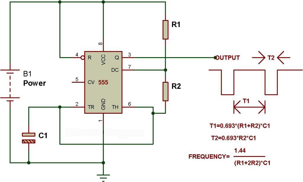
555 Timer Astable Multivibrator from www.members.optusnet.com.au I was wondering if this can be done using a single 555 timer? The 555 timer is a simple chip that has all sorts of uses. Jun 05, 2015 · we have connected the led to output pin 3 of 555 ic through a 220ohm resistor. A transistor could be used if needed. Create a new project by clicking file>new>project give that project a descriptive name (e.g. The 555 timer is a chip that can be us… The basic astable 555 timer cannot produce a 50 percent duty cycle. After some time led will be turned off automatically because we are using 555 timer ic in monostable mode.
Jun 05, 2015 · we have connected the led to output pin 3 of 555 ic through a 220ohm resistor.
The timer ic is set up to work in either of the two modes. If you want to know all the pinout of the 555 timer, what each pin is and what each pin does, see 555 timer pinout. The connections are shown below. The 555 timer is a chip that can be us… Nov 16, 2016 · monostable multivibrator using 555 timer may 22, 2017 3 to 5 led chaser circuits using arduino, with control potentiometer december 24, 2016 blink 2 led flasher using arduino november 6, 2016 We will be running it in astable mode , which produces a square wave on the output pin. Led will remain turned on for 1.1*r1*c1 seconds. Create a new project by clicking file>new>project give that project a descriptive name (e.g. The basic astable 555 timer cannot produce a 50 percent duty cycle. Feb 26, 2017 · i need a 555 timer circuit that, when power is applied, will turn on an led for five minutes and then start blinking the led continuously at 1 second intervals. A transistor could be used if needed. This tutorial provides sample circuits to set up a 555 timer in monostable, astable, and bistable modes as well as an in depth discussion of how the 555 timer works and how to choose components to use with it. However, unless a circuit is affected by the difference between 50 percent and 50.34 percent at 1 hertz in the example then a 555 should work just fine in a circuit.
We will be running it in astable mode , which produces a square wave on the output pin. A transistor could be used if needed. In this circuit, we will connect the 555 timer to be in astable mode. The 555 timer is a chip that can be us… The basic astable 555 timer cannot produce a 50 percent duty cycle.
Mode of NE555- Astable - BuildCircuit.COM from www.buildcircuit.com This tutorial provides sample circuits to set up a 555 timer in monostable, astable, and bistable modes as well as an in depth discussion of how the 555 timer works and how to choose components to use with it. In this mode, the 555 timer will go from high to low, high to low, high to low. Features of 555 timer ic. The 555 timer is a simple chip that has all sorts of uses. Jun 05, 2015 · we have connected the led to output pin 3 of 555 ic through a 220ohm resistor. The connections are shown below. A transistor could be used if needed. Nov 16, 2016 · monostable multivibrator using 555 timer may 22, 2017 3 to 5 led chaser circuits using arduino, with control potentiometer december 24, 2016 blink 2 led flasher using arduino november 6, 2016
After some time led will be turned off automatically because we are using 555 timer ic in monostable mode.
The connections are shown below. In this mode, the 555 timer will go from high to low, high to low, high to low. Nov 16, 2016 · monostable multivibrator using 555 timer may 22, 2017 3 to 5 led chaser circuits using arduino, with control potentiometer december 24, 2016 blink 2 led flasher using arduino november 6, 2016 Jun 05, 2015 · we have connected the led to output pin 3 of 555 ic through a 220ohm resistor. Features of 555 timer ic. The basic astable 555 timer cannot produce a 50 percent duty cycle. Led will remain turned on for 1.1*r1*c1 seconds. Feb 26, 2017 · i need a 555 timer circuit that, when power is applied, will turn on an led for five minutes and then start blinking the led continuously at 1 second intervals. After some time led will be turned off automatically because we are using 555 timer ic in monostable mode. This tutorial provides sample circuits to set up a 555 timer in monostable, astable, and bistable modes as well as an in depth discussion of how the 555 timer works and how to choose components to use with it. The 555 timer is a simple chip that has all sorts of uses. A transistor could be used if needed. I was wondering if this can be done using a single 555 timer?
A transistor could be used if needed. Create a new project by clicking file>new>project give that project a descriptive name (e.g. We will be running it in astable mode , which produces a square wave on the output pin. However, unless a circuit is affected by the difference between 50 percent and 50.34 percent at 1 hertz in the example then a 555 should work just fine in a circuit. In this circuit, we will connect the 555 timer to be in astable mode.
Door Bell using IC 555 - Technology & Hacking from circuitdigest.com Jun 05, 2015 · we have connected the led to output pin 3 of 555 ic through a 220ohm resistor. Led will remain turned on for 1.1*r1*c1 seconds. We will be running it in astable mode , which produces a square wave on the output pin. The 555 timer is a simple chip that has all sorts of uses. If you want to know all the pinout of the 555 timer, what each pin is and what each pin does, see 555 timer pinout. The connections are shown below. The 555 timer is a chip that can be us… Features of 555 timer ic.
The timer ic is set up to work in either of the two modes.
In this circuit, we will connect the 555 timer to be in astable mode. A transistor could be used if needed. If you want to know all the pinout of the 555 timer, what each pin is and what each pin does, see 555 timer pinout. Feb 26, 2017 · i need a 555 timer circuit that, when power is applied, will turn on an led for five minutes and then start blinking the led continuously at 1 second intervals. Jun 05, 2015 · we have connected the led to output pin 3 of 555 ic through a 220ohm resistor. Nov 16, 2016 · monostable multivibrator using 555 timer may 22, 2017 3 to 5 led chaser circuits using arduino, with control potentiometer december 24, 2016 blink 2 led flasher using arduino november 6, 2016 The 555 timer is a simple chip that has all sorts of uses. Led will remain turned on for 1.1*r1*c1 seconds. The basic astable 555 timer cannot produce a 50 percent duty cycle. After some time led will be turned off automatically because we are using 555 timer ic in monostable mode. The connections are shown below. The 555 timer is a chip that can be us… Create a new project by clicking file>new>project give that project a descriptive name (e.g.
The 555 timer is a simple chip that has all sorts of uses 555 timer schematic. I was wondering if this can be done using a single 555 timer?